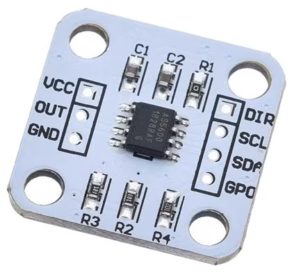
AS5600 12-Bit Magnetic Position Sensor
Component/Hub

The as5600 sensor platform you to use your AS5600 (datasheet,
AMS) or AS5600L (datasheet,
AMS) 12-bit magnetic position sensor with ESPHome. Individual sensors will be added
using the AS5600 Sensor Platform. To use this hub, first setup
the I²C Bus and connect the sensor to the pins specified there.

as5600:
  dir_pin: GPIOXX
  start_position: 0deg
  range: 180deg
Configuration variables
dir_pin (Optional, int): The pin connected to the AS5600’s direction pin. See Direction for more information.
direction (Optional, string): The direction that the magnet should rotate to increase values. Used in combination with the dir_pin.
clockwise(default)counterclockwise
start_position (Optional, int): The raw position that should be considered the start (i.e.
0). See Position / Range.end_position (Optional, int): The raw position that should be considered the end (e.g. 180deg) of the allowable rotation range. Mutually exclusive with range. See Position / Range.
range (Optional, int): The allowable rotation range from the start_position. Mutually exclusive with end_position. See Position / Range.
hysteresis (Optional, string): See datasheet.
none(default)lsb1lsb2lsb3
power_mode (Optional, string): The power mode to run the sensor. Note: When watchdog is enabled, it will switch the device to
low3when there is not much change in position.nominal(default)low1low2low3
watchdog (Optional, boolean): Whether to enable the watchdog that puts the the chip in to low power mode 3. Check the datasheet for more information. Defaults to
off.slow_filter (Optional, string): See datasheet.
16x(default)8x4x2x
fast_filter (Optional, string): See datasheet.
none(default)lsb6lsb7lsb9lsb18lsb21lsb24lsb10
address (Optional, int): The i²c address of the sensor. See I²C Addresses for more information.
id (Optional, ID): Manually specify the ID for this AS5600 Hub.
All other options for I²C devices described at I²C Bus.
Direction
The AS5600 has direction pin that controls which rotation direction will cause the position value to increase.
This pin should be pulled low for clockwise, and pulled high for counterclockwise. If left floating, you are likely
to encounter erratic behavior.
If you would like the ESP controller to pull that pin high or low, you may configure the dir_pin and optionally, the
direction option to have the ESP controller pull the pin high or low.
Position / Range
Position and range may be configured as one of the following:
- a value between
-4095and4095 - an angle between
-360degand360deg - a percentage between
-100%and100%
ℹ️ Note
Negative position values will be normalized to their respective positive position (e.g. -90deg would translate to 270deg).
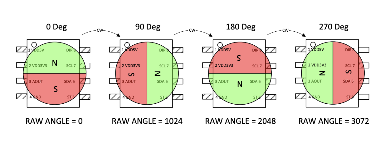
The AS5600 reports 2 position values. The value for both types of position values will always be a whole number between 0 and 4095.
A “raw” position value is not filtered, scaled, etc. So a value of 0 is always when the north end of the magnet is at the top of
the chip, 2048 is always when the north end of the magnet is as the bottom of the chip, etc.
The regular/scaled position is filtered and scaled based on the sensor configuration (e.g. start_position, end_position, range, etc).
For example, let’s say we have the following component config:
as5600:
  start_position: 90deg
  range: 180deg
  direction: clockwise
dir_pin: GPIOXX- If the magnet north was at the right side of the chip (i.e. 1024 / 90deg raw position), the scaled position would report a value of
0. - If the magnet north was at the bottom of the chip (i.e. 2048 / 180deg raw position), the scaled position would report a value of
2048. - If the magnet north was at the left of the chip (i.e. 3096 / 270deg raw position), the scaled position would report a value of
4095. - If the magnet north was at the top of the chipe (i.e. 0 / 0deg raw position), the scaled position would be out of range (which also has it’s own caveats discussed below).
ℹ️ Note
You may specify an
end_positionthat is less than thestart_position. When doing so, the allowable range will start at thestart_positionand continue through to the highest position value (i.e.4095) and then continue from0until it reaches theend_position.
⚠️ Warning
The datasheet calls out that the minimum angle that can be configured (start and end position, or start and range) it 18 degrees. Configuring anything less than that may yield un-expected results.
I²C Addresses
The AS5600 address is not configurable and must be 0x36. However, if using an AS5600L,
the default address should be 0x40 and it is configurable.
Sensor
The as5600 sensor allows you to publish the angle/position measurement from your AS5600 with ESPHome.
First, setup an AS5600 Hub for your AS5600 sensor and then use this
sensor platform to create individual sensors that will report the position to Home Assistant.
as5600:
  dir_pin: GPIOXX

sensor:
  - platform: as5600
    name: Position
    raw_position:
        name: Raw Position
    gain:
        name: Gain
    magnitude:
        name: Magnitude
    status:
        name: Status
Configuration variables
out_of_range_mode (Optional, string): How to treat out of range values. Only applicable if configured for a range less than 360 degrees. Defaults to
min_max. See Out of Range Mode.as5600_id (Optional, ID): Manually specify the ID of the AS5600 Hub you want to use this sensor.
update_interval (Optional, Time): The interval to check the sensor. Defaults to
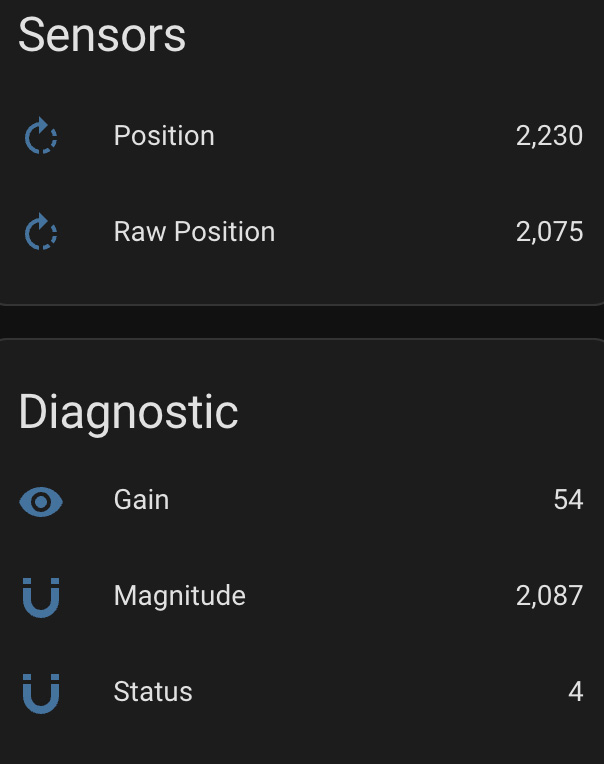
60s.raw_position (Optional): Reports the raw (un-scaled, un-filtered) position of the magnet.
- All other options from Sensor.
gain (Optional): Information about the automatic gain control. Typically for diagnostic purposes. The datasheet says this will be between 0-255 when powered by 5v and between 0-128 when powered by 3.3v. Ideally the value should be close to the middle of the respective range.
- All other options from Sensor.
magnitude (Optional): Information about the detected magnitude. Typically for diagnostic purposes. The expected scale does not appear to be defined in the datasheet, however, AMS provides a user guide which contains pictures that show it as a scale between
0and3000. Typically this value is seen somewhere in the neighborhood of2100for a well positioned magnet.- All other options from Sensor.
status (Optional): Information about the magnet status. Typically for diagnostic purposes. See Magnet Status
- All other options from Sensor.
All other options from Sensor.
Out of Range Mode
min_max(default)nan
When using a range less that 360deg, there would be a range of raw values that would be considered “out of range”. By default (min_max mode), the AS5600
splits that range in half and reports 0 while in the half of the “out-of-range” range closest to the start_position and it reports
4095 while in the half of the “out-of-range” range closest to the end_position / end of the range. Alternatively, you may set to nan
mode where the sensor will publish NAN (i.e. “Unknown”) when the position falls outside the narrowed range.
Magnet Status
The magnet status should report one of the following values:
2indicates that no magnet was detected.4indicates that the magnet was detected and has good reading.5indicates that the magnet was detected, but is too strong. Measurements may appear to be stuck if the magnet is too strong.6indicates that the magnet was detected, but is too weak. Measurements may still be possible in this state.
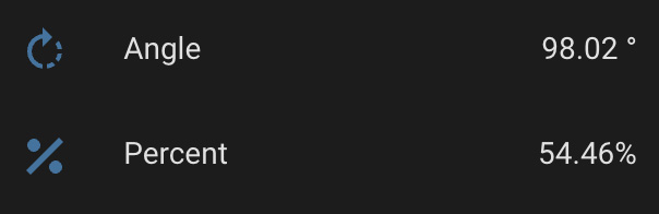
Converting Position
You may desire the position to be converted from the native 0 thru 4095 to degrees, or perhaps a percentage of the allowable range.
Here are some examples to make that happen:
as5600:
  id: my_as5600
sensor:
  - platform: as5600
    update_interval: 1s
    name: Angle
    unit_of_measurement: '°'
    accuracy_decimals: 2
    icon: mdi:rotate-right
    filters:
      - delta: 1
- lambda: 'return x * as5600::RAW_TO_DEGREES * id(my_as5600).get_range_scale();'as5600:
id: my_as5600
sensor:
- platform: as5600
update_interval: 1s
name: Percent
unit_of_measurement: '%'
accuracy_decimals: 2
icon: mdi:rotate-right
filters:
- delta: 1
- lambda: 'return (x / as5600::POSITION_COUNT) * 100;'